Technical Background
To monitor SID events a VLF radio transmitter and a VLF radio receiver is needed. For most of us it is impossible to operate or obtain a strong VLF radio transmitter. But there are plenty of those transmitters operated by national agencies and the military. Monitoring the field-strength of transmissions from those VLF radio transmitters does not provide any details on the actual messages transmitted. What one is interested is only the variation of a more or less known standard signal. This variation of a field-strength is a measure of for the phenomena occurring in the ionosphere. In the following the simple SID monitoring hardware utilized for the InFlaMo project is described.
InFlaMo Network Instrumentation
To monitor effects of the lower ionosphere a simple single frequency (actual narrow band) VLF radio receiver and a suitable antenna is needed. Such a set-up is suitable for especially K-12 projects to demonstrate basic effects. A more complex VLF radio receiver is recording a broader spectrum and can be utilized for advanced studies of the lower ionosphere. For both systems a (passiv) loop antenna or an active antenna system can be utilized.
Sinlge frequency (narrow band) VLF receiver
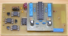
Despite the fact that we discuss here a narrow band VLF radio receiver, at the InFlaMo project we call this receiver type a single frequency SID monitor. The motivation for this somehow incorrect name giving was to outline the fact that this SID monitor is recording data (field-strenght) from only one transmitter station (assuming that the recording band width is narrow enough to avoid any overlays from other transmitter station frquencies). To archive this goal we utilize a self-designed and relatively easy to understand and set-up circuit board (see picture on the left). The analog data are transmitted to a modern LINUX-micro-PC. The data can be read and processed with ordinary script languages. This concept offers a large scale of opportunities for educators and K-12 students to explore the world of radio wave propagation, electronics and computer sciences.
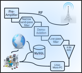
How does a narrow band VLF radio receiver works? Obviously is the world not as narrow as we would wish in this matter. LF and VLF signals are transmitted on a broad spectrum and are detected by a, e.g. loop antenna. So let us assume this means that the input signal (RF) is a signal consisting out of all possible frequencies. This RF signal is at first processed by pre-amplifier, which enhances the signal. This process is followed by narrow band-pass filter. Here the target transmitter frequency together with a narrow frequency band surounding is extracted from the main spectrum. A demodulation of the remaining signal follows. This results in a DC voltage level, which is equal to the signal strength. After processing this signal once more with a low-pass filter one has only an analog signal as left-over and can convert it via an 8 Bit analog-digital-converter (ADC) into digital informations, which can be transmitted for processing to a Linux-micro-PC. An user can now analyse the data (manual or automated) and/or store them at data-storing facility. Other users from the world wide web can also access this data-storing facility or even upload their data for further science projects.
Broadband VLF and LF receiver
A broadband radio wave receiver is nothing else everybody of us knows nowadays as a FM radio. To listen to the local radio station we are able to tune this FM radio on a frequency range somewhere within the MHz range. It has become common that the somewhat large FM radios of the 20ies century are hidden today within peoples cell phones and are no longer based on the transistor technology of the 1960ies. Those modern FM radios are as a matter of fact so-called software defined radios (SDR).
A SDR, is a radio communication system where components that have been typically implemented in hardware (e.g. mixers, filters, amplifiers, modulators/demodulators, detectors, etc.) are instead implemented by means of software on a personal computer or embedded system.We no longer see large antennas (in the case of the cell phone the cable of the headset is actually an antenna).
A basic SDR system may consist of a personal computer equipped with a sound card, or other analog-to-digital converter, preceded by some form of RF front end. Significant amounts of signal processing are handed over to the general-purpose processor, rather than being done in special-purpose hardware. Such a design produces a radio which can receive and transmit widely different radio protocols (sometimes referred to as waveforms) based solely on the software used.
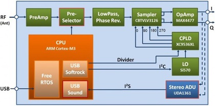
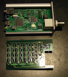
First SDR systems have been developed in 80ies and were aimed primarily for military use.Today SDR systems start to be affordable and radio amateurs have developed low priced and high quality hardware suitable for science applications. This sudden development has made it possible to utilize SDR receivers also with broader bandwidth (e.g. ~10Hz till 60 MHz) for ionospheric studies aiming to investigate VLF and LF waves. While we are used to listen to just one radio channel on our FM radio, it is possible to record (listen) a continious spectrum with a SDR receiver at a high temporal resolution. This makes the SDR the (almost) perfect ionospheric phenomena measurement device. For the InFlaMo project we utilize the FiFi-SDR (see picture beside).
Antennas utilized for InFlaMo SID receivers
For a single frequency SID monitor one may choose between a loop antenna or an active antenna setup. In principle the broadband SID monitor should be operated with an active antenna setup, but it is known to work with the simple do-it-yourself loop antenna, too. In the following both antenna types are introduced.
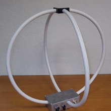
A simple do-it-yourself loop antenna
At first one must ask what is a loop antenna (see picture on the left) and why use it? For LF and VLF radio wave receiving one would need in principle very long metal wires (to build a large di-pole). The same may be archived by using a loop antenna, which is a small multi turn loop of less than 1/10th wavelength in length. There are many ways on how to wind the loop form. It may be either box (solenoid), any solenoid (e.g. a pentagon) or a spiral (pancake) wound. As core material one may choose from air or a powdered iron compound (Ferrite). The easiest solution is to use air.
A disatvantage of the loop antenna to the longwire is that the gain is much less. On the other hand it has much less noise (electrical component) to pick up. A properly designed Loop primarily responds to the magnetic component of the radio wave. A vertical antenna responds mainly to the electrical component. That means that the loop antenna can be orientated towards the direction of the transmissions magnetic field vector. That means that the area of the loop must be perpendicular to the transmissions magnetic field vector in order to obtain strongest signal strength. So one must compute the direction of the in-coming signal and orientate the area of the loop antenna perpendicular to this direction. More about that and the general theory of loop antennas is extensively explained by Lionel Loudet.
The twin-loop antenna design
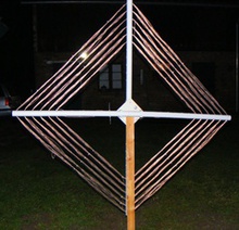
An example for a not so simple do-it-yourself twin loop antenna was given by Vladimir Skripachev and Yu Polushkovsky from Moscow State Technical University of Radio Engineering, Electronic and Automation. They constructed the antenna shown on the left for the Moscow site of the InFlaMo Project, which operates a SuperSID from Stanford University.
This is a kind of twin-loop antenna system made for better performance than a single loop B-field antenna. The geometry allows reception of a wider VLF spectrum without setting up the antenna in certain postition, e.g. towards the direction of a transmitter. For more details on different VLF antenna designs visit the page: Antennas for VLF radio reception.
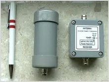
The PA0RT Mini Whip active antenna
This is an electric field active antenna in a small package. If it is accepted that a whip is a capacitance coupled to the electric field, shape becomes irrelevant, as long as the required capacitance is available. In practice the “whip” can be e.g. a small piece of copper clad printed circuit board. A small die-cast aluminium box can also be used, with the buffer amplifier mounted inside. Following this line of thought, tests have been performed to find the optimum dimension for the pa0rdt-Mini-Whip. To prevent receiver overload, maximum output has been set to about – 20 dBm. The buffer amplifier has been optimised for good strong signal handling performance. This antenna type has been selected as the 'perfect' fit for our broadband VLF SID monitor.
A detailed technical describtion written by the developer Mr. Roeoff Backer can be found here. The picture on the left provided by curtesy of Mr. Roeoff Backer. Although Mr. Backers PA0RT Mini Whip active antenna is a great fit for our hardware, there are alternatives, too. The B3CKS VLF antenna project does demonstrate how to build an active VLF antenna with low-budget parts.
How to obtain your own SID monitoring equipment?
Depending on what are your aims, your background, of course the budget and skills you first must decide what kind of SID monitor is suitable for you and/or your team. Above are the single and the broadband SID monitors described. But before that you may wish to consider if you have a suitable location to set up such an experiment. VLF radio waves receiving may be difficult in dense populated regions, where there are plenty of man-made disturbances (hospitals, EMT-/fire-/police-services, airports, armed forces bases etc.). Even if your location is in the country there may be trouble with dense bio-masses (e.g. forest, larger and dense bushes etc.). Once you have made a survey of your location you may want to contact the InFlaMo project for advice.
Then you must decide if you wish to buy a ready made SID monitor or build one from scrap or as a ready kit by yourself. This might be nice as a K-12 project. Here you want to ensure that you have electronic equipment to tune the filters. If you do not have this possibilities but still wish to build, e.g. a single frequency SID monitor by yourself, then again contact us from the InFlaMo project for support.
You have a modest budget and no time to build your own SID monitor then it may be best that you order a ready to use device. Again there are plenty of sources you may want to consider:
- order from one of the many SID observer groups one of their devices, or
- order form the InFlaMo project one of the above described instruments
In any case the InFlaMo project team will be happy to support you and provide addresses, links and prices.